
There is an app called Scoppy which is particularly designed for this application. And to detect the square wave or sine wave you can feed the signal to your Mobile phone. A simple oscilloscope using Raspberry Pi Pico and some passive electronics can be made. In this project, I will show you how you can make your own Oscilloscope using the Raspberry Pi Pico and your Smartphone. We can design a simple DIY SmartPhone Oscilloscope using a microcontroller at a very low price probably at 5$ only. If you are an electronics hobbyist or some technician and if you are unable to buy these, then here is a solution for you. When you go through the pricing of a commercial oscilloscope, you will realize it is not affordable for beginners. There is a standard oscilloscope for lab and industrial applications. You can use multimeters as well, but the problem with multimeters is that they aren’t fast enough to detect the signals. Sometimes when you repair some electronics hardware and do some Research and Development work, you need an Oscilloscope.

In this article you learn to make your own DIY SmartPhone Oscilloscope using Raspberry Pi Pico and Scoppy.

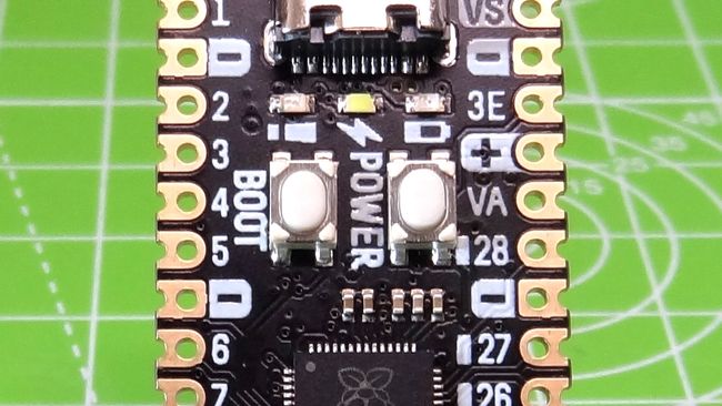
The new is the RP2040, which will emulate the RAM, programmable clock, video, USB host, storage and SID player. The old is the MOS 6502 CPU, a popular CPU in the early days of 20th century home computer era. The Neo6502 is an attempt to merge the old and new into one package. This project is an attempt to see "is it possible to build a modern peripheral 6502 computer that is with the lowest possible cost," according to Olimex founder Tsvetan Usunov. The reason for the extra GPIO is for another Olimex project, the Neo6502. USB C also provides a power source that can provide up to 3A, and a SY8089A DC to DC voltage regulator will ensure that there is 3.3V at 3A. I prefer this over micro USB as it feels more robust, and I do not have to worry about correctly guessing the orientation. A welcome addition to RP2040-PICO30 is a USB C connector for data and power. The RP2040-PICO30 removes four GND connections in order to squeeze a few more GPIO pins into the pinout, while retaining general compatibility. The pinout for the Raspberry Pi Pico has 40 pins in total, with the remaining 10 used for multiple GND connections, 3.3V, 5V and ADC voltage reference. Four pins are reserved for controlling the power supply (GPIO23), USB detection (GPIO24), status LED (GPIO25) and monitoring the power supply (GPIO29). The standard pinout for the Raspberry Pi Pico and Raspberry Pi Pico W has 26 GPIO pins, which can be controlled by the user.


 0 kommentar(er)
